How a Radio Antenna works
A transducer is a device that converts one physical quantity into another.
The antenna is a transducer, and the conversion takes place between an "electric current" and an "electromagnetic field".
There are two types of antennas: a Transmitter Antenna and a Receiver Antenna.
The transmitting antenna converts the electric current generated by the transmitter into an electromagnetic field that is radiated.
The receiving antenna converts the received magnetic field into an electric current. The receiver uses this electric current to extract the information it contains.
What is the purpose of an FM antenna
It is used to transmit music, thoughts, pictures, etc. by way of electromagnetic energy and radio waves.
An FM antenna does just that.
We see antennas every day: they are in our cell phones, in our cars, in our homes.
Antennas come in many different shapes. The shape depends on what you intend to receive or transmit.
So the function of an antenna is either to send radio waves all over the earth, and even into space, or to receive radio waves from long distances.
What does a Radio Antenna compare to?
The operation of the antenna is less intuitive than that of other transducers.
To compare it to something more familiar we can think about speakers.
We all listen to the radio, the TV or Hi-Fi systems; we are familiar with how the speaker converts an electrical current into acoustic energy or sound waves.
We are used to listening to music at different volumes: the speakers inside headphones, the speakers used at rock concerts. The first use only fractions of watts to produce the sound we hear, while the others use many thousands of watts!
In layman's terms, the antenna does what the speakers do, only it converts to electromagnetic – not acoustic – energy.
There are antennas connected to small transmitters that radiate a few tens of watts, and antenna systems connected to transmitters of thousands of watts.
What kind of antennas are there?
There are two types of antennas: a transmitter type, and a receiver one – the latter being the one more commonly used.
Both work differently, but in related, complementary ways.
How does the whole Transmitter-Antenna-Receiver system work?
The transmitter receives electrical audio signals as input, and transforms them into radio frequency.
The antenna, connected to the transmitter, transforms the radio frequency into radio waves also called electromagnetic waves.
Radio waves travel at the speed of light and can travel great distances around the earth and even into space.
These radio waves are captured by the receiving antennas.
Once captured, they generate an electrical current that a radio or other similar device converts into electrical current and then into sound or data.
A radio station uses an FM antenna to transform the radio frequency produced by the transmitter into electromagnetic waves and thus transmit its signal over long distances.
What is the difference between the transmitting antenna and the receiving antenna?
The transmitting antenna has a very different characteristic from the receiving one.
The transmitting antenna must handle high power, must direct the waves in the area of interest, must be mounted at a height that allows it to reach as far as possible.
The receiving antenna – that of the car, for example – must receive signals of very low power from any direction.
Important properties of Transmitting Antennas
Four characteristics of antennas are particularly important: directionality, gain, bandwidth and polarization.
Directionality
Directionality is the parameter that measures in which direction is the greatest radiation of the antenna or, in other words, in which direction there is the greatest concentration of radiation.
Antennas are divided into two types: Omnidirectional and Directional.
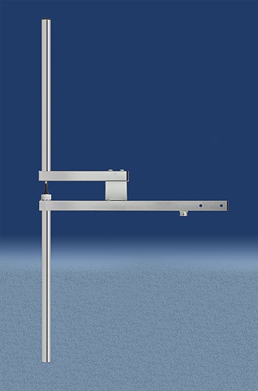
Omnidirectional antennas radiate equally in all directions: 360 degrees. This is the antenna called DIPOLO. The most widely used.
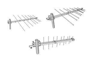
Directional antennas can be of different types: Multiple Element antennas, Logarithmic antennas, Yagi antennas and Panels.
Each of these types has different values of directionality and of concentration of the electromagnetic beam in one direction.
Gain
In electromagnetics, the gain of an antenna is a number that combines antenna directivity and electrical efficiency.
In a transmitting antenna, the gain describes how much the antenna converts incoming power into radio waves radiated in a specific direction.
A relative parameter is used to define antenna gain: the ratio of the power radiated by the antenna in a specific direction to the power radiated by a hypothetical lossless isotropic antenna that is equally radiated in all directions.This ratio is expressed in decibel-isotropes (dBi). dBi is the parameter normally used to specify the gain of an antenna.
It should be specified that given a specific type of antenna, the gain is a parameter that depends on the geometry of the antenna and cannot be changed by the manufacturer to improve or worsen it.
For example, in order to increase the gain of a dipole antenna the only possible operation is to increase the number of antennas.
A two antenna system has twice the gain of a single antenna. A four antenna system has twice the gain of a two antenna system, and so on.
Bandwidth
The geometric shape or size of the FM antenna is an inverse ratio to the wavelength of the signal to be transmitted.
Outside the working band the antenna is mismatched.
The matching parameter defines how much the antenna shows itself to the transmitter as a pure 50 Ohm load. Pure in the sense that it must show itself as a purely ohmic, non-capacitive and non-inductive resistor.
In a mismatched antenna part of the power is reflected, sent back to the transmitter in the form of VSWR.
This produces two effects:
1) Power is not radiated so coverage decreases;
2) The transmitter is overloaded because it has to handle the power it is transmitting plus the power that is being sent back.
This overload can damage the transmitter.
The above considerations imply that the bandwidth is a finite number, and that it is difficult to design antennas that cover a very wide band; increasing or decreasing the frequency of the signal, you go out of the band for which the antenna was designed.
If, for example, you double the FM frequency, the size of the antenna becomes half.
Conversely, if the frequency is halved with respect to the FM frequency, the antenna increases twice in size.
There are two types of antennas: Wideband and Tuned.
Wideband FM antennas maintain their matching characteristic in all 20MHz of the FM band.
Tuned antennas are adapted only in a small band around the frequency to which they were tuned.
The FM bandwidth is 20MHz: consequently, because of the above, designing an antenna that has a consistent matching characteristic throughout the band requires special attention and skill when designing it.
The matching of a wideband antenna is something that the designer and manufacturer can work on to improve: that is, to ensure that the impedance presented by the antenna to the transmitter in all points of the band is the best possible as well as constant throughout the band.
Polarization
Polarization is the direction in which the electromagnetic fields produced by the antenna travel when energy is radiated.
These directional fields determine the plane along which the energy travels and is received by a receiving antenna.
This plane is conventionally called the "E-plane".
Polarization can be Linear (vertical, horizontal or oblique) or Circular.
This simple concept is important for antenna-to-antenna communication.
A horizontally polarized antenna will not communicate with a vertically polarized antenna and vice versa.
Linear Polarization
Linear polarization refers to an antenna system that operates with polarization in a single plane of radiation: vertical, horizontal, or oblique.
For vertical polarization, the electric field will oscillate up and down in a vertical plane.
For horizontal polarization, the electric field will oscillate left and right on a horizontal plane.
Thus, a vertical antenna receives and emits vertically polarized waves, and a horizontal antenna receives or emits horizontally polarized waves.
Circular Polarization
In circular polarization, the E-plane, or the direction in which the energy is radiated, changes continuously with a circular motion.
This means that the vector of the E-plane continuously rotates and gradually passes through all intermediate variants from vertical to horizontal.
In this type of polarization, the power of the transmitter is radiated on two vectors, the vertical and the horizontal one.
The power on the single vector then becomes half.
Choosing the polarization type
The choice of the type of polarization depends on the regulations in force in the country where the antenna is used.
The most used globally is vertical polarization.
In some Eastern European and Northern European countries horizontal polarization is or used to be used.
In the United States and Latin America circular polarization is used.
The choice of the type of polarization is either political or technical.
Horizontal polarization was chosen to avoid the reception of radios from neighboring countries.
Circular polarization is used with the belief that it improves reception, mainly in cars or in large cities.
In this last case, we must consider two factors:
1) the electromagnetic beam, rotating, makes the antenna receive the signal in any position it is;
2) the power received is half of that it could receive if radiated in one direction only.
Antennas in cars are mounted at 45 degrees: this way, they can receive any kind of polarization.
However, it also true that by doing so they receive a signal which is halved compared to the one they would receive if the antenna was positioned in the same axis of the transmitting antenna.

