STL-R3-B
STL Link Receiver
Band 820-960MHz
The high quality SOUND on the market-STL Link Receiver audio signals coming from the Studio several miles away-B820-960MHz-On stock-Immediate delivery

GENERAL DESCRIPTION
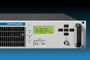
This transmitter and its companion receiver
are the core of a high quality, synthesised studio-to-transmitter link
(stl), to be used for broadcast repeaters in conjunction with any
standard FM or AM transmitter. They are an evolution of the previous
extablished series stl whose main circuitry is still extensively used
here with a new controller, user interface and software and more
advanced oscillators in a compatible 2u 19" case. They allow the
reception of mono or stereo signal and its retransmission without
using any additional stereo-coder on the receiving end: in both cases
the LF output signal from the receiver must be sent to the stereo
input (linear or not pre-emphasised) of the local FM rebroadcast
transmitter.
The stl is built for several different frequency slots from VHF to
the SHF range. Two main models are built: one for the 200÷960 MHz and
the other for the 1300÷2500 MHz range. While the exterior cabinet, the
controls, the basic circuitry and the performances are the same, some
internal components vary or are specifically tuned as required to
cover this wide frequency band. Usually these components are the local
oscillator, the power amplifier and the input/output filters The
factory adjusted frequency slots are 10 to 50 MHz wide and must be
specified in the order. In the preset sub-range, the frequency and
power of the transmitter may be freely changed on the field. The
receiver may require some more adjustment for wider frequency
displacement: in fact the adoption of narrow, low loss input filters
permitted to achieve the best possible rejection of interfering
signals in the band at the expense of some frequency agility. So
nearly 8-10MHz may be used without any retouching but wider variation
up to 50-60MHz will require retuning of the input filter.
Being the apparatuses completely digitally controlled, they are
extensively on field programmable by front panel or remotely in every
respect. The alphanumeric display permits easy and accurate metering,
adjustment and continuous monitoring of modulation levels, power,
operation and internal parameters. All these information are
externally available on the same RS232 I/O port that may be used to
remotely control the transmitter. In addition to the serial I/O,some
signals and controls are available on a parallel I/O socket for easy
interfacing with others analog controllers or supervisory systems. A
powerful 3-levels password management permits a very high degree of
security and privacy as may be required in different situations.
The LF input and output levels are precisely adjustable over a broad
range, by means of 0.5dB stepwise variable attenuators. The
transmitter has also an auxiliary input, specifically designed for RDS
and SCA encoders. A modulation monitor output permits to control other
transmitters or STL's with the same internally processed high-quality
mpx signal. Furthermore, the system is optimised to be compatible with
external digital companding encoder/decoders and to provide RDS and
SCA signals, with almost no attenuation.
Optional top-quality stereo encoder/decoder boards may be factory installed on the transmitter/ receiver or field retrofitted with minimum required technical skill. The powerful internal software and monitoring functions recognise their presence and enable the functions. A universal switch-mode power supply permits operation in the extended 95-250 V ac range with no intervention and a 24 V back-up battery input is provided too.
TECHNICAL FEATURES RECEIVER
Like the Transmitter, the Receiver front panel accommodates the single control knob, the display, four leds for immediate status control and a single output connector for IF monitoring.
Here too regular operation is signallized by green leds: "PLL Lock" and "Field". This latter is a bi- stable and lights in yellow when RF field is too low or absent. As in the Transmitter red leds signals improper operation. The first one, "Modulation", is activated by low or absent modulation; the last one is the general "Alarm" led.
The Receiver I/O connectors on the rear panel are:
- The mains supply IEC320-type outlet, which incorporates the mains switch and the fuses. An additional earth screw for system earthing and a 24V-battery backup socket pair. In alternative the mains outlet with fuse-holder and the mains switch may be separate components
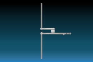
- The RF antenna connector, N-type
- The main composite signal output (Mpx+, Mpx-) on two BNC-type
connectors in antiphase, permitting direct drive of two separate
transmitters or one in balanced mode.
- A buffered LF monitor, BNC-type connector that may be internally
connected as an additional composite or wide-band or mono signal
output.
- The filtered/de-emphasised mono signal on a balanced male XLR-type
connector.
- The L & R audio channels output sockets on balanced XLR-type
connectors (only with internal Stereo Decoder option).
- A RS232 Dsub9 female remote serial control port, inverted wired.
- A parallel control port, Dsub9 male type
RADIO LINK TRANSMITTER-RECEIVER TECHNICAL FEATURES
| PARAMETER | VALUE |
|---|---|
| Factory preset frequency ranges | 215÷245Mhz 240÷270Mhz |
| 300÷340 Mhz 340÷380 Mhz | |
| 400÷440 Mhz 430÷470 Mhz | |
| 810÷850 Mhz 850÷890 Mhz | |
| 890÷930 Mhz 930÷960 Mhz | |
| 1350÷1375 Mhz 1370÷1390 Mhz | |
| 1429÷1433Mhz 1510÷1530Mhz | |
| 1660÷1670Mhz 2367.5÷2372.5Mhz | |
| 2440÷2.450Mhz 2468.1÷2483.3Mhz | |
| Modulation | FM, 75 kHz peak dev. |
| 180kF3E mono | |
| 256kF3E stereo | |
| Synthesis step | 10kHz (215÷960 Mhz) |
| 25kHz (1.3÷2.5Ghz) | |
| Composite Mpx output response | 15 Hz ÷ 67 kHz +0.1/-0.5dB |
| <-6 dB @ 100 kHz | |
| <-20 dB @ 125 kHz | |
| Monitor output wide-band response | 15 Hz ÷ 100 kHz +0.1/-1.5dB |
| -3 dB typ. @ 125 kHz | |
| -6 dB typ. @ 160 kHz | |
| Mono/stereo decoded response | 30 Hz ÷ 15 kHz ±0.2dB |
| S/N ratio (30÷20000Hz rms) | >75 dB, 80 typ. mono |
| >72 dB, 76 typ. stereo | |
| Modulation distortion(100%dev.) | |
| @1kHz/ | mono ≤0.1% 0.03% typ. |
| stereo,1ch ≤0.30% 0.20%typ. | |
| @ 30÷7500 Hz | mono ≤0.25% 0.12%typ. |
| stereo,1ch ≤0.30% 0.20%typ. | |
| Stereo crosstalk(typical) | >50dB(400÷10000Hz) |
| >40 dB (100÷15000 Hz) | |
| I/Olines | Alarm, RF/LFdisable, Low RF field |
| remote control/lock | |
| RS232 for monitoring and control | |
| Mains requirements | 110 - 240 V~ 50/60 Hz |
| 24 V= | |
| Operating temperature range | 0÷35° C recomm. |
| -10÷45 °C max |
RADIO LINK RECEIVER TECHNICAL FEATURES
| PARAMETER | VALUE |
|---|---|
| Noise figure | ≤9dB |
| Image frequency rejection | ≥60dB 70typ. |
| Dynamic selectivity | >+10dBtyp@δF=300kHz |
| >+35dB typ @ δF=500 kHz | |
| >+45dB typ @ δF=1.0 MHz | |
| AM suppression | >45dB |
| Usable input level | -90÷-10dBm |
| (7μV÷70mV) | |
| Sensitivity (typical) | Sin=-90dBm(7μV) mono |
| (S/N=60dB) Sin=-70dBm(70μV)stereo | |
| IF monitor output | 10.7MHz/0dBm |
| Wide-band demodulated output response | 15 Hz ÷ 120 kHz +0.1/-3dB |
| Wide-band demodulated output level | +6dBm |
| MPX output level | -1.5 ÷ +12 dBm, 0.5dB/step |
| Mpx output response | 15 Hz ÷ 67 kHz +0.1/-0.5dB |
| mono or stereo decoded response | 30 Hz ÷ 15 kHz ±0.1dB |
| Out-of-band mono or stereo audio response | >50 dB @ F≥19 kHz |
| De-emphasis time constant | 0/50/75μs±2% |
| S/Nratio(30÷20000Hz.rms) | >72 dB, 76 typ. Mono |
| >70 dB, 73 typ. Stereo | |
| Modulation distortion @1kHz/100%dev. | mono ≤0.1% 0.03% typ. |
| stereo, 1ch ≤0.30% 0.20%typ. | |
| Stereo crosstalk | >50 dB(100÷5000Hz) |
| >45 dB (50÷15000 Hz) | |
| I/O lines | LF disable, Low RF field, Alarm, RS232 control and monitoring |
| Mains absorption | 15Wmax@110-240V~ |
| Battery absorption | ≤0.4A@24V= |
| Dimensions, without handles | 19" 2 un. std. Rack |
| 483x88x330mm |
Recommended products
no products avaible
 BACK TO STL STUDIO LINK


